
August was one step forward but the other step going nowhere. The cable installation started as planned and is proceeding to schedule with the first 500m laid between the hydro site at Havannah and Eaton Bank Academy. The second 500m is currently in the process of being installed and the link into the Siemens factory will be complete in the next couple of weeks.
Not just a length of wire but an essential part of the performance of the overall project, so it deserves a special focus and attached to the newsletter is an article that describes the cable itself, the installation process (not simple to lay approx.1Km of 3” diameter cable!!) and some of the associated regulations and technicalities that help define the choice of cable and the inevitable compromise between cost and performance. We hope you find the article informative.
Unfortunately going nowhere was our plan to start the civil construction work on site. As mentioned in the last newsletter we were planning to start site work on August 3rd. We thought everything was all in place but had not really foreseen that the turning radius of the articulated lorry (bringing the material to construct the access trackway) was greater than the width of the available portion of the carriageway of the Macclesfield road. Various bits of brainstorming did not find a timely solution, but the good news is that access is now sorted, and site work commenced on Tuesday, September 1st. This short delay does extend our completion date to end mid- February although we will endeavour to work with CTC to recover schedule as much as possible—if only the weather will stay fair!
One of the portions of the civil works is the construction of the inlet water system (in days gone by this would have been called the “leat”) that delivers water from upstream of the Weir to the inlet structure of the Archimedes screw. The cost/performance of this inlet water system has always been a slight niggle so the “free time of August” has been put to good use to find the best cost-performance solution. We hope you find the following few paragraphs of interest and help you appreciate the degree of design detail that goes into trying to achieve the optimum performance of the system.
When it came to specifying the design of the turbine inlet pipe nothing was quite as straight forward as it would seem.
Some background info. The amount of mechanical power that can be theoretically generated by the Archimedes screw (Pth) is, among other things, a function of the falling height of the water (the so-called driving head (H)) according to the formula.
- Pth = power theoretically available (W)
- ρ = density (kg/m3) (~ 1000 kg/m3 for water)
- Q = water flow (m3/s)
- g = acceleration of gravity (9.81 m/s2)
- H = driving head (m of water)
So, the smaller the value of H, the less power can be generated.
Practically speaking, H is a measurement of the difference in the height of the water in the forebay tank which feeds water into the turbine, compared with the river level at the turbine outlet.
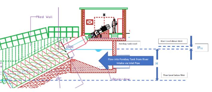
For many schemes like ours the water level in the forebay tank is effectively the same as the level of the water at the crest of the weir. However, not so for the Congleton hydro scheme which relies on a 30m long-buried inlet pipe to feed the water from the intake structure located upstream of the weir to the forebay tank.
Gravity takes care of forcing the water through the inlet pipe but for this to work the level in the forebay tank must be slightly lower than the river level at the intake. (Water generally flows downhill). This difference in these heights is known as the inlet pipe head loss IPHL. The greater the value of IPHL, the smaller the value of the available driving head H and the less power the turbine can generate.
The inlet pipe head loss IPHL for a given flow rate is, in turn, a function of the pipe diameter as well as the roughness of the inside surface of the pipe. Larger pipes result in lower water velocities and lower head loss. Rough pipes surfaces impose more friction which in turn causes more head loss. The number and angle of any pipe bends, as well as the shape of the pipe inlet and outlet, also contribute to the size of IPHL
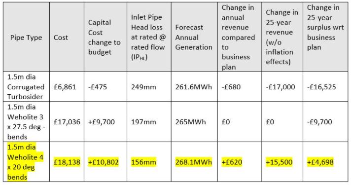
The Conundrum: The original design and the financial model for the Congleton Hydro scheme was based on the total inlet pipe head loss (IPHL) being no more than 200mm. This implicitly assumed the use of a smooth (low friction) pipe. However, it was much to our surprise when we recently discovered our cost estimation for constructing the scheme had been based on the use of a much less expensive corrugated pipe with a significantly higher friction loss. The difference in price between the corrugated pipe and the smooth pipe of equivalent size and design was greater than £10,000. However, the head loss through the corrugated pipe was determined to be 249mm vs 156mm through the smooth pipe. This might not sound much of a difference given the nominal overall design driving head (H) for the scheme is 3800mm, however over an extended period it would amount to a significant loss in power generation and revenue.
The Solution: To resolve this problem we looked a variety of different designs options in terms of their material, geometry, cost, associated head loss and other factors to arrive at the most cost-beneficial solution.
Potentially the most obvious and least expensive solution would have been to have specified a slightly larger corrugated pipe diameter to compensate for the increased friction factor. An increase from1500mm to 1800mm diameter would have apparently done the trick in terms of reducing the head loss. However, while the larger pipe itself was relatively inexpensive, the additional cost associated with the enlargement of the excavation and a more complex transition piece between the head wall and the pipe together ruled out this option. In addition, there was a concern about the buried depth of such a pipe being reduced to less than 0.3m.
We also looked at using smooth concrete pipe in both round and square sections. While the head losses were acceptable to cost was prohibitive.
The table below illustrates the impact on the capital cost of the project for 3 of the several options considered versus the predicted power generation of the scheme, the change in revenue and the resulting surplus cash after 25 years of operation according to the business plan. Clearly over a 25-year period, the 4-bend Weholite is the best option and should slightly improve the surplus cash generated. Corroborating this decision, was the possibility that the corrugated pipe would be more susceptible to fouling than a smooth pipe resulting in its actual performance being even worse than shown above. The chosen pipe is now on order and the delivery fits well into the overall project plan.
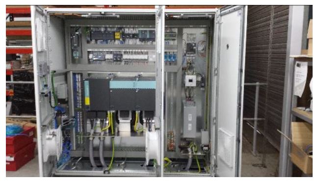
The concept of an Archimedes Screw generating electricity from the water flow over the weir might sound relatively simple, but as we have just seen the size and type of pipe has quite an impact on system performance. The control system to enable it to happen automatically and safely 24/7 is quite complex. We mentioned in the last newsletter that the control cabinet with integrated Siemens variable speed drive, gearbox and generator had been donated to us by local company HMK. Work has started in August to determine the programme needs of the system to meet the needs of and optimise the performance of our hydro system.
The essence of the control system is to regulate the braking torque and speed of the Archimedes screw and convert the braking energy into electricity.
The requirement of the abstraction licence granted by the Environment Agency is that the level of water over the weir is controlled (i.e. it must never run dry due to too much water bypassing it and flowing through the Archimedes screw). The faster the screw turns, the more water flows through and the more electricity is generated, but if the water level drops too much it must slow down. Obviously, the amount of water available depends heavily on the amount of upstream rainfall.
Speed and torque control is achieved using an industrial 3-phase induction generator connected to a variable speed drive (VSD), which electronically generates a variable frequency voltage and applies it to the stator windings of the 3-phase induction generator. When braking torque is being applied to the generator, the energy from the VSD is converted back into the electricity grid using a so-called active front-end. This controls the voltage and phase of the ac waveform it generates with respect to the grid voltage at the Siemens sub-station to ensure that all the generated power is exported into the grid.
The whole system is supervised by a Programmable Logic Controller (PLC) which generates start-up and run-down sequences, including the control of a hydraulically operated sluice gate and a thruster-controlled disc brake. It also regulates the speed to keep the water level stable. Supervised monitoring and emergency stop system ensures that no single component or wiring failure can result in the screw running at an uncontrolled speed. The PLC, which has been programmed from scratch in ladder logic using the Siemens Totally Integrated Automation (TIA) programming tools, includes an HMI (visualisation screens) and can be accessed remotely via a 3G data link.
So, despite the poor turning circle of an articulated lorry preventing the earthworks starting, August has, in the overall scheme been a very productive month.
We have also started to look at the details of the Education programme—what do we hope to achieve? what the various modules will be? how will we prepare them? and crucially important how we will deliver them? The Education programme will be a key focus of next month’s Newsletter and especially the volunteers who are needed to help design, prepare, and deliver the various modules.
Being an embryonic organisation, we are starting from scratch with just about everything. Indeed, this is the case with Volunteers who are needed to maintain the scheme and we are now in the process of identifying the specific activities and the role responsibilities e.g. as mentioned above, the Education programme.
Volunteering has much to offer people, regardless of their age. For young people, the hydro project offers a living example of the importance of sustainability and the protection of the environment and will do much to support the school’s curriculum. For older volunteers, the hydro project will offer an opportunity to use their skill sets to help the organisation and also an active and productive activity for people who might otherwise have a sedentary lifestyle. Volunteers unite people from a wide range of backgrounds, abilities, and a wide geographic area, supporting social cohesion and generating friendships.
Next month’s newsletter will, as well as a focus on the Education Programme, take a detailed look at the volunteer opportunities and the headline role responsibilities presented by the Hydro scheme. In the meantime, we welcome input from anybody who has an interest in volunteering—please drop a note to contact us.
A big thank you to those who have already contacted us.
As mentioned last month, essential to the smooth and rewarding running of the volunteer activity is the role of the Volunteer Manager/Co-ordinator. Just in case you missed it last time, the role description is attached. Even if this does not interest you for whatever reason, it would be much appreciated if you could forward to family, friends, colleagues who might possibly be interested.
As with previous newsletters, we hope you have found this edition to be of interest and informative. We would welcome any feedback and suggestions for improvement, future topics etc please contact us.
So, until next month please stay safe and take care and please, please keep your fingers crossed for fine weather to help with the site work progress!!!
As mentioned earlier, this month’s short article is all about the Cable Connecting our Power to the Customer is available to download above. Not just a length of wire but a crucially important element in the success of the Hydro System. We hope you find it informative and if you have any questions or require further information please contact Paul Hopewell.
Recent Comments